La placa L298N es llamada un "puente-H". Se utiliza para controlar la velocidad y sentido de giro de dos motores DC. Puede gobernar motores DC con voltajes entre 5 y 35V con corrientes de pico de hasta 2A. Se necesita cuando queremos controlar motores porque las entradas/salidas de Arduino no permiten directamente tanta corriente eléctrica de salida (FanIN/FanOUT).
(Asegúrate que la polaridad de ambos motores es la misma en las dos entradas. De otra forma girarán en sentidos inversos)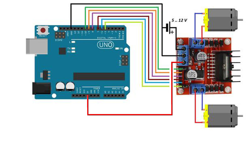
L298N pinout
Este es el significado de los pines de este módulo para controlar motores
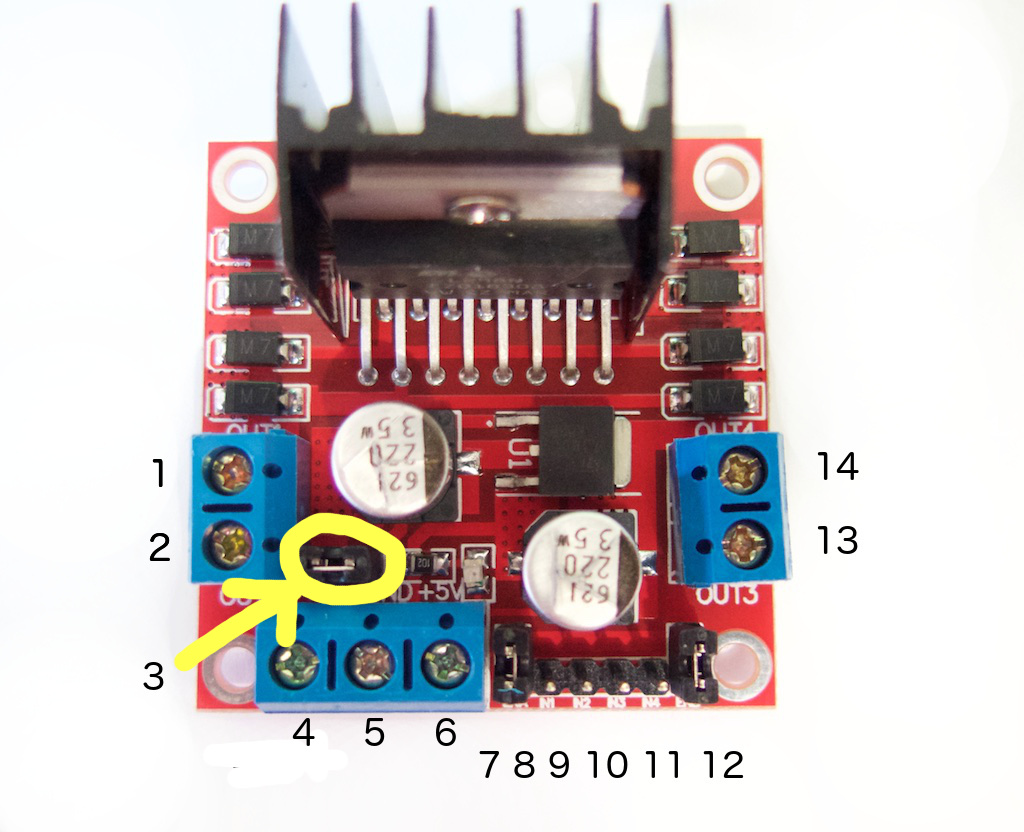
- Motor 1. Positivo (o motor paso a paso A+)
- Motor 1. Negativo (o motor paso a paso A-)
- 12V jumper - quita este jumper si usas más de 12V DC como alimentación. Esto habilita el regulador a 5V que lleva esta placa.
- Conecta la alimentación de los motores aquí. Entre 5 y 35V DC. (Quita el jumper 3 si >12V DC)
- GND
- Salida a 5V si está colocado el jumper de 12V. Es ideal para alimentar tu Arduino (etc)
- Jumper para habilitar el Motor 1 DC. Déjalo cuando uses un motor paso a paso. Connect to PWM output for DC motor speed control.
- IN1
- IN2
- IN3
- IN4
- Jumper para habilitar el Motor 2 DC. Déjalo cuando uses un motor paso a paso. Conecta a una salida PWM para control de velocidad de motores DC.
- Motor 2. Positivo (o motor paso a paso B+)
- Motor 2. Negativo (o motor paso a paso B-)
Controlando Motores DC
To control one or two DC motors is quite easy. First connect each motor to the A and B connections on the L298N module. If you're using two motors for a robot (etc) ensure that the polarity of the motors is the same on both inputs. Otherwise you may need to swap them over when you set both motors to forward and one goes backwards!
Next, connect your power supply - the positive to pin 4 on the module and negative/GND to pin 5. If you supply is up to 12V you can leave in the 12V jumper (point 3 in the image above) and 5V will be available from pin 6 on the module. This can be fed to your Arduino's 5V pin to power it from the motors' power supply. Don't forget to connect Arduino GND to pin 5 on the module as well to complete the circuit.
Now you will need six digital output pins on your Arduino, two of which need to be PWM (pulse-width modulation) pins. PWM pins are denoted by the tilde ("~") next to the pin number, for example:

Finally, connect the Arduino digital output pins to the driver module. In our example we have two DC motors, so digital pins D9, D8, D7 and D6 will be connected to pins IN1, IN2, IN3 and IN4 respectively. Then connect D10 to module pin 7 (remove the jumper first) and D5 to module pin 12 (again, remove the jumper).
The motor direction is controlled by sending a HIGH or LOW signal to the drive for each motor (or channel). For example for motor one, a HIGH to IN1 and a LOW to IN2 will cause it to turn in one direction, and a LOW and HIGH will cause it to turn in the other direction.
However the motors will not turn until a HIGH is set to the enable pin (7 for motor one, 12 for motor two). And they can be turned off with a LOW to the same pin(s). However if you need to control the speed of the motors, the PWM signal from the digital pin connected to the enable pin can take care of it.
This is what we've done with the DC motor demonstration sketch. Two DC motors and an Arduino Uno are connected as described above, along with an external power supply. Then enter and upload the following sketch:
El CI L293 tiene las siguientes características:
- Se pueden controlar hasta 2 motores.
- Proporciona 1A a los motores (en total) y permite cambiar el sentido de giro.
- Utiliza un puente en H que funciona según se observa en las figuras (internamente utiliza transistores para conmutar*) :
![]()
Modos de operación para invertir el sentido de giro:

"H bridge operating" by Cyril BUTTAY - own work, made using inkscape. Licensed under CC BY-SA 3.0 via Wikimedia Commons.
*Datasheet: http://www.me.umn.edu/courses/me2011/arduino/technotes/dcmotors/L293/l293.pdf
Código del programa de prueba
(recuerda alimentar a Arduino y al L298N):
----------------------------------------------------------------------------------------------------------------------------
// connect motor controller pins to Arduino digital pins
// motor one
int enA = 10;
int in1 = 9;
int in2 = 8;
// motor two
int enB = 5;
int in3 = 7;
int in4 = 6;
void setup()
{
  // set all the motor control pins to outputs
  pinMode(enA, OUTPUT);
  pinMode(enB, OUTPUT);
  pinMode(in1, OUTPUT);
  pinMode(in2, OUTPUT);
  pinMode(in3, OUTPUT);
  pinMode(in4, OUTPUT);
}
void demoOne()
{
  // this function will run the motors in both directions at a fixed speed
  // turn on motor A
  digitalWrite(in1, HIGH);
  digitalWrite(in2, LOW);
  // set speed to 200 out of possible range 0~255
  analogWrite(enA, 200);
  // turn on motor B
  digitalWrite(in3, HIGH);
  digitalWrite(in4, LOW);
  // set speed to 200 out of possible range 0~255
  analogWrite(enB, 200);
  delay(2000);
  // now change motor directions
  digitalWrite(in1, LOW);
  digitalWrite(in2, HIGH);
  digitalWrite(in3, LOW);
  digitalWrite(in4, HIGH);
  delay(2000);
  // now turn off motors
  digitalWrite(in1, LOW);
  digitalWrite(in2, LOW);
  digitalWrite(in3, LOW);
  digitalWrite(in4, LOW);
}
void demoTwo()
{
  // this function will run the motors across the range of possible speeds
  // note that maximum speed is determined by the motor itself and the operating voltage
  // the PWM values sent by analogWrite() are fractions of the maximum speed possible
  // by your hardware
  // turn on motors
  digitalWrite(in1, LOW);
  digitalWrite(in2, HIGH);
  digitalWrite(in3, LOW);
  digitalWrite(in4, HIGH);
  // accelerate from zero to maximum speed
  for (int i = 0; i < 256; i++)
  {
    analogWrite(enA, i);
    analogWrite(enB, i);
    delay(20);
  }
  // decelerate from maximum speed to zero
  for (int i = 255; i >= 0; --i)
  {
    analogWrite(enA, i);
    analogWrite(enB, i);
    delay(20);
  }
  // now turn off motors
  digitalWrite(in1, LOW);
  digitalWrite(in2, LOW);
  digitalWrite(in3, LOW);
  digitalWrite(in4, LOW);
}
void loop()
{
  demoOne();
  delay(1000);
  demoTwo();
  delay(1000);
}
----------------------------------------------------------------------------------------------------------------------------
Este es un vídeo demostrativo del funcionamiento de este programa
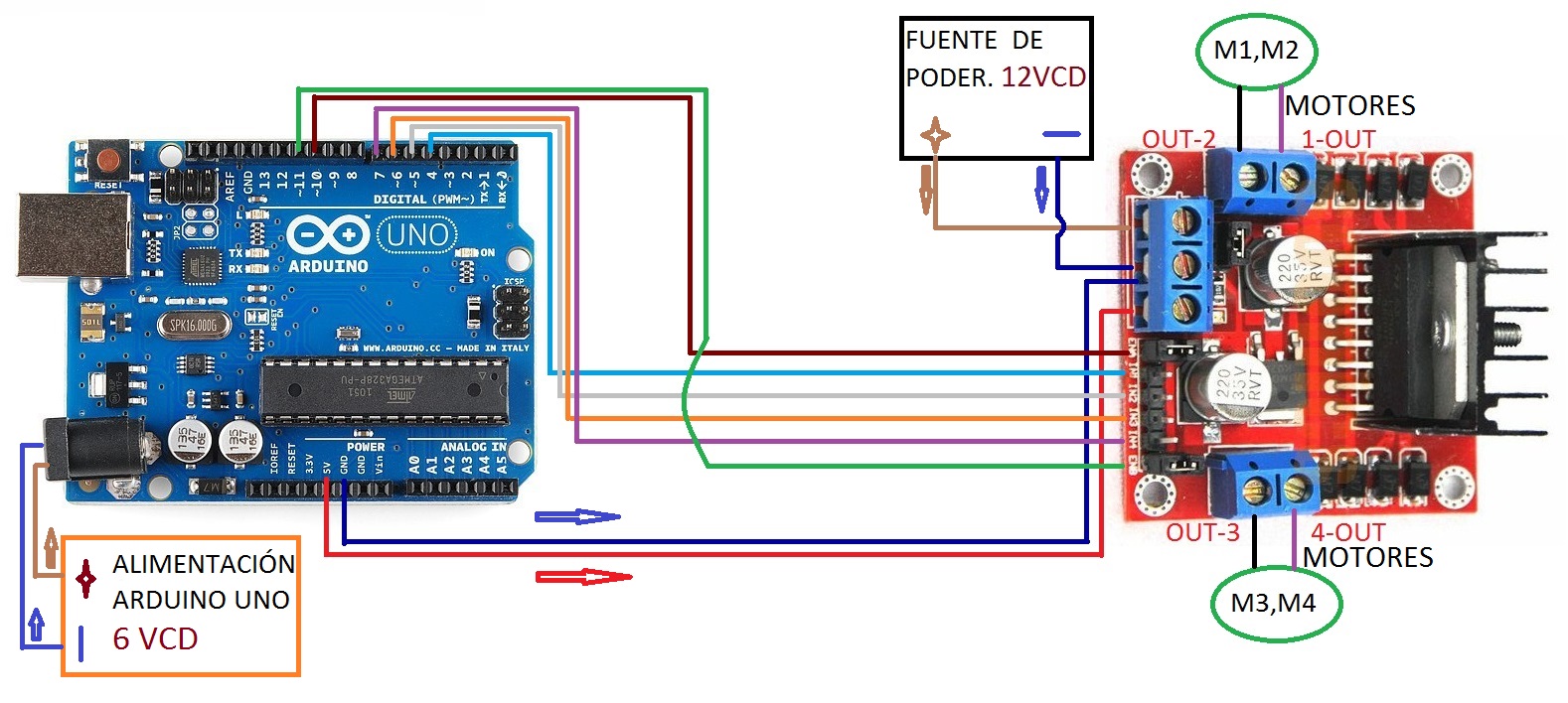
Otro esquema similar al anterior, pero en lugar de usar los pines 5,6,7,8,9 y 10 usa 4,5,6,7, 10 y 11.
Fíjate que se necesitan 4 salidas PWM (las que tienen el símbolo ~)
Si quieres profundizar más: Control de dos motores mediante el móvil con bluetooth. Necesitarás un módulo bluetooth y alguna de las muchas apps gratuitas de control de Arduino bluetooth que se encuentran en la Play/App Store